|
The
Trend Setter

Part
3
ONE-WIRE
compared to
THREE-WIRE
ALTERNATORS
What Happens when the
ONE-WIRE cannot do Remote Voltage-Sensing
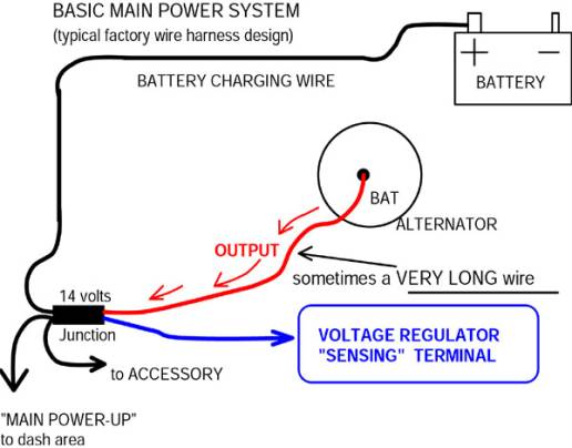
All voltage regulators
for alternator systems will have a “VOLTAGE SENSING”
terminal. The
voltage regulator for the “ONE-WIRE” system gets the
voltage reading from within the alternator, and it will
maintain the alternator out-put terminal at about 14.2
volts. Lack
of compensation for voltage drop that will occur with a
long wire routed to a “MAIN POWER DISTRIBUTION
JUNCTION” is the problem with being able to read voltage
only at the alternator.
In many factory-original wiring systems, the
entire electrical system will draw power from the main
junction, and the battery will charge from the
main junction too. If we have a 2.5 volt drop in the long length of wire between
the alternator and the “main junction,” and start out
at the alternator with 14.2, then we only have 11.7 volts
at the main junction. Expect dim lights, weak ignition, and slow electric
radiator fans with this system being powered by a
“ONE-WIRE” alternator.
Please note
that simply disconnecting the original alternator wires,
and then installing a heavy cable from the alternator
directly to the battery, will only make the alternator
effective as a “battery charger.”
(That happens when running a ONE-WIRE alternator
with many factory layouts.)
Of course we have to charge the battery, but what
about routing power from the alternator to the electrical
system? (ignition,
lights, and accessories)
Power would have to flow from the battery to the
junction via the old “charging wire.”
And often in a factory-original type harness the
“charging wire” is even longer than the wire from the
alternator to the junction.
And so the result of this ONE-WIRE method would be
dimmer lights and overall weak electrical system
performance; in fact often worse performance than with the
original, correctly wired, small alternator that was
standard equipment on the old cars.
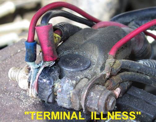
Okay, all these modern
accessories that come with instructions to connect a wire
directly to the battery POS, and the instruction to
connect a cable from the ONE-WIRE directly to the battery,
has resulted with a clutter at the battery area.
And thanks to the 100 amp ONE-WIRE alternator (a
high rate battery charger indeed), the wires are a
corroded, unreliable, mess!
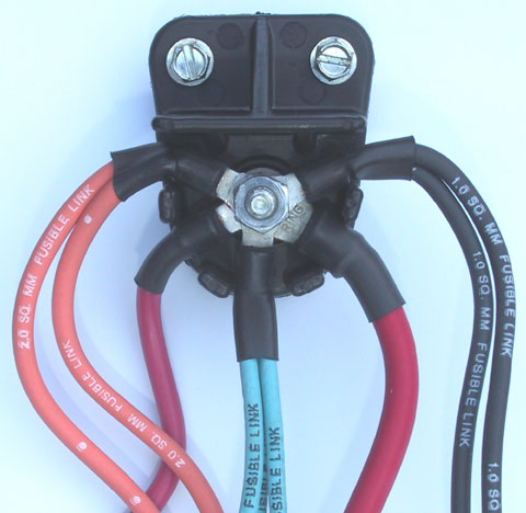
The part#CN-1, insulated
terminal block, from M.A.D.’s catalog, is a sensible
method of connecting a few wires together.
It has a re-enforced shield above it to shed water,
and separators between wires.
It’s a great little organizer in general.
And it will be mounted remote from the battery,
where it will stay free of corrosion.
Value of Remote
Voltage-Sensing with THREE-WIRE
The well laid-out factory
system will have the voltage regulator taking the
“VOLTAGE SENSING” sample directly from the “MAIN
JUNCTION,” through a wire dedicated to this function.
And that was true with both the external and the
internal voltage regulator systems.
And it’s the reason that the old external voltage
regulator stayed at the driver’s side when the
alternator got moved to the opposite side, beginning with
’69 models (Chevy V-8 engines).
As lighting or any
accessories are switched ON, more power is drawn from the
main junction, which would lower voltage at the junction.
But the voltage regulator will increase alternator
output as needed to maintain the 14 volt level at the
junction. If
we have a 2.5 volt drop in the wire between the alternator
and the junction, then the voltage regulator will make the
alternator produce 16.5 volts to compensate for the
voltage drop with routing of power to the junction.
It’s a somewhat
“spongy” system, but it does work well and the
alternator doesn’t know the difference.
Expect bright lights, strong ignition, powerful
accessories, and a properly charged battery when this
system is wired effectively.
When running with the factory-original type wire
harness, clearly it is an advantage to maintain the
“MAIN POWER DISTRIBUTION JUNCTION” at 14 volts.
ELECTRICAL SYSTEM
PERFORMANCE
When voltage available to
electrical parts drops about 10% below optimum level, the
performance of the parts will typically drop by about 30%.
If voltage delivered to parts is only a little low,
performance can be very weak.
(Lights will be dim, electric fans will not move as
much air, fuel pumps will be low with fuel pressure
delivery, and so on, when these parts operate at low
voltage.) Most
automotive electrical parts are rated at about 14 volts.
And the parts will deliver best performance and
last the longest when operating at 14 volts.
A couple of very
important considerations
regarding this
factory-original type system, which uses a main power
distribution junction, and remote voltage sensing.
(And of course M.A.D.
did not invent the system, we are just observing operation
of a system that was successfully used for many years.
And it is a system that we understand well enough
to up-grade, make it friendly for addition of accessories,
and make it stronger to accommodate a more powerful
alternator operating more powerful accessories.)
(1)
The system only works properly when the “battery
charging wire” connects from the junction to the
battery. There
will never be a wire connected from the alternator
directly to the battery.
By now the thought may
have occurred, that a possible installation could include
a heavy gauge charging wire from the alternator directly
to the battery. And
then leave in place the original wire from the alternator
to the factory main junction. Route the voltage sensing
wire to the junction, in effort to keep the lights and
ignition happy. It’s
true that then voltage regulator would maintain the
junction at the 14.2 level.
However, the fault in the plan is with the voltage
drop that will occur between the alternator and the
junction. As was previously discussed, the system will
compensate by raising the voltage level at the alternator.
The problem would be overcharging the battery
through the separate charging wire, as voltage at the back
of the alternator could be over 16 volts.
(2)The
second important consideration of the typical Muscle Car
period factory system is the effect of the long battery
charging wire (which routes from the junction to the
battery). It’s
a rare occasion when a little resistance in wiring can
actually help us, and this is one of those rare occasions.
A small amount of resistance in the “charging
wire” leg of this system will serve as a cushion.
The amount of resistance will be much too small to
be measured with an ordinary ohmmeter, as accuracy of the
ohmmeter will only be good to about a plus or minus 0.2
ohm. But the
amount of resistance can be calculated after measuring
current flow and voltage drop.
To understand how this
“cushion” effect with a small resistance at the
charging wire works, we must first have knowledge of how
batteries behave when being charged.
When recharging a low battery, battery voltage will
be low, and current flow (amps) to the battery will be a
large amount. As
the battery becomes charged, battery voltage increases,
and it will accept less charge, so charging current (amps)
will decrease. Eventually
during charging, battery voltage reaches the level of the
voltage setting at the charger, and the battery stops
accepting all but a very small amount of current.
(See more about how
discharged batteries behave when being charged, in photos
and captions, at our “RE-CHARGING LOW BATTERIES” page,
in this tech section.
And see more about special maintenance battery
chargers at our BATTERY CHARGING for MAINTENANCE and
STORAGE page in this tech section.)
When working with more
than a 60 amp alternator, the actual amount of resistance
at the “charging wire,” and also the wire from the
alternator to the junction, should always calculate to
less than 0.1 ohm. The
actual amount of resistance will vary with wire length and
wire gauge sized used in various models, and the amount of
resistance will also change with temperature.
(A warm wire conductor will have more resistance
than a cool wire conductor.)
A new or good condition, factory built harness on a
Chevy from the Muscle Car period will have about 0.02
to 0.05 ohm resistance at the wire from the alternator
to the junction, and about the same at the charging wire
from the junction to the battery.
RESISTANCE IN THE
“CHARGING WIRE” /
FULLY CHARGED BATTERY
For our calculations, we
will use a 0.05 ohm resistance, which is a
middle-of-the-road number, for an average Chevy factory
harness. The
battery will be charged from the junction in the wire
harness, and voltage at the junction will be maintained at
14.2 volts. With
the battery in a fully charged condition, it will accept
less than 1 amp, from a 14.2 volt source.
We will use 1.5 amp for the charge rate, which is a
battery approaching fully charged condition.
The math formula (from Ohm’s Law) can be used to
easily calculate the amount of voltage drop that will
occur with the small amount of resistance at the
“charging wire” between the junction and the battery.
The math formula gives us that Voltage (drop) =
current flow (amps) X resistance (ohms).
With the numbers used for this example, 1.50 amps X
0.05 ohms = 0.075 volt(drop).
Rounded off to the nearest 1/100th of a
volt, that is a 0.08 volt drop.
And so, with 14.20 volts at the junction, we have
14.12 volts at the battery, which is fine.
(Individual voltage regulator settings will vary
more than 0.08 volts.)
The small amount of resistance in this wiring
system does not have significant effect on charging the
battery, when the battery becomes fully charged.
Voltage drop is a very small amount, when the
current flow is a small amount (through the small amount
of resistance at the charging wire).
RESISTANCE IN THE
“CHARGING WIRE” /
DISCHARGED BATTERY
When charging current is
delivered to a discharged battery at a full 14.2 volt
level, the battery will accept a large amount of current
(amps). And
when charging a large capacity battery, if the battery
charger or alternator is sufficiently powerful, the amount
of current can be a large amount.
In that case we can expect the battery to get warm
and produce excessive gas (which results with short
battery life and a corroded mess at the battery area).
The battery charger or alternator will produce a
significant amount of heat too, so it will need a good
cooling capacity. (With
both the battery and the alternator, it’s back to that
efficiency loss situation where heat is the by-product.
The low battery
being charged by the alternator is a situation when the
small amount of resistance in the charging wire will help
us. Power
from the junction will reach the battery at a reduced
voltage level; which automatically reduces the charge
rate. We could do calculations for this situation, like we did
above with demonstration of system performance when the
battery is fully charged.
However with the discharged battery situation we
don’t have constants.
Resistance in the
charging wire causes voltage drop with current flow to the
battery, and the voltage drop reduces current flow.
Current flow is also reduced as the battery becomes
charged. We
begin with a discharged battery that cannot produce full
voltage on its own. Then
as the battery accepts current it becomes more charged and
produces more voltage, and then the battery accepts less
current flow. In
this battery being re-charged situation, the system is not
“static,” it is a changing and self-adjusting system.
The small amount of resistance at the “battery
charging wire” makes it is a very gentle and
“forgiving system.”
The system is
conservative as it helps to prevent battery gassing,
battery overheating, and alternator overheating. The small
amount of resistance in the “charging wire” does not
prevent the battery from reaching a fully charged
condition; with a small resistance it will just take a
little longer to top off the battery with charge.
(And when using a 100 amp alternator, it can be a
very good idea to slow down the charging rate!)
And…while
all the above is happening, ignition, lighting, and
accessories are being powered-up from the main junction,
and at a 14 volt level–and 14v regardless of battery
condition! (The exact voltage level will be the setting of
the voltage regulator, and we assume that the alternator
is capable of operating all the accessories plus charge
the battery). All
aspects, considered the factory layout using a “main
junction” and “remote voltage sensing” is an
incredibly effective system.
Although when the alternator is replaced with a
more powerful model, and added accessories draw more power
from the system, then the wiring for the system must also
be up-graded.
It has never been a
good idea to re-charge a low battery with the alternator.
But there are those times when we are caught by
surprise… It’s easy enough to accidentally leave the
lights on when far away from home.
Or an electric fan run-on function can run the fans
longer than the battery can stand.
Eventually the time can arise when we need a
jump-start, and then we will drive to our destination.
And with a high powered alternator in place, these
are the times when a system like the factory lay-out with
a properly wired THREE-WIRE alternator system could really
help us out, by slowing the charge rate.
(A low battery should be re-charged with a workshop
type charger. The
alternator is intended to keep the battery topped off and
operate the electrical system.)
A POSSIBLE PROBLEM
with installing a more powerful alternator and
using the existing factory wiring is that when those older
cars were built, the wire gauge sizes were calibrated for
much less powerful alternators than we are using today.
And back when those cars were built, we were not
operating so many powerful accessories.
Nowadays electric radiator fans are a common
example of an added accessory that will strain the
existing system.
Voltage
drop resulting from a small amount of resistance spread
out over a long length of wire will behave quite
differently than a small amount of resistance at a
“bottleneck.” With
voltage drop, the electrical energy lost is converted to
heat. (Again,
energy is never lost or destroyed–only converted.)
In the case of a short length, under-capacity wire,
or in the case of a poor connection, we have resistance at
a small area, and this bottleneck effect can result with
destruction of the part through “thermal run-away.”
When we spread the small amount of resistance out
over a long length of wire, the voltage drop and heat
generated is also spread out over the length of the long
wire; and then the heat can be dissipated without
overheating the wire.
But as with stress limitations of any machinery
part, there are limitations with this wiring system too.
(A thorough discussion and explanation of
“thermal run-away” effect is contained in the “tech
is made simple” book, available from M.A.D.
A
typical ’65 Chevy was often shipped with only a 37 amp
alternator, and the wiring was adequate for that much
output. The
wire from the output terminal of the alternator was often
only 12 gauge, with early alternator systems.
The wiring will have to be up-graded on those early
cars, when we use more powerful alternators and
accessories.
The
current capacity of factory systems in various cars from
the Muscle Car period will differ considerably.
But Chevy is more popular than ever before; we will
use Chevy for an example. The ’69 –’71 Chevy with V-8 engine uses a system like
the diagram in this feature.
The passenger side mounted alternator has a very
long wire from the alternator to the main junction.
The junction is a “welded splice,” in the loom,
at the driver’s side.
The wire routing is a very long semi-circle between
the alternator and the junction.
And the “battery charging wire” is also very
long, to get from the junction back to the battery at the
passenger side. At
least in these years of Chevy cars, the alternator output
wire and the battery charging wire are both 10 gauge
wires. A 63
amp model 10SI works very well with existing wiring in
that system, and the factory built 78 amp 12SI will work
well with this system too. But remote voltage sensing from the junction should always be
used with up-grades to SI alternators.
When
adding electrical accessories with significant current
draw, and the SI alternators to this existing Chevy
system, it is very important that the accessories are
powered from the wiring at the junction–rather than
connected directly to the alternator or to the battery.
But the factory “welded splice,” hidden in the
wire harness is not friendly to work with.
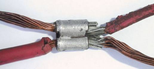
The
photo above shows a close-up view of an actual
“junction” from a Chevy wire harness.
Four red, 10 gauge wires were all connected
together, at what we have labeled a “junction” in our
system diagram. (The
GM engineering department refers to the junction as a
“welded splice.”
“Buss-bar” would also be correct terminology
with this discussion.)
This type of junction, hidden in the wire harness,
is very reliable, and it was economical to manufacture;
but it is not friendly for up-grade work.
The “junction” does not lend itself to system
modification or adding wires for accessories. The
insulated terminal block (part#CN-1, from M.A.D.) seen in
the photo below is a very friendly to work with
“junction,” and it should be used when up-grading this
system.
On the “flip side” of our
systems comparison, expect
that
with a 100amp ONE-WIRE alternator, wired directly to the
battery, and the same ’69-’71 Chevy wiring system,
performance of the electrical system parts will be
significantly reduced.
Wiring from the alternator directly to the battery
will charge the battery, but that could be done with a 37
amp alternator too. The
performance problem will come from “back-feeding”
power through the old charging wire to the junction.
Driving with lights and factory accessories
switched ON, we can have a 30 to 35 amp current load
through that 0.05 ohm resistance at the old charging wire.
And then we will have a 1.5 to 1.75 volt drop in
the old circuit, which is now feeding power to the
junction. This
situation would result with the junction delivering power
to various parts of the electrical system at only 12.45 to
12.7 volts, which is no better than just running off the
battery!
Also,
if we ever have the need to recharge a discharged battery
while driving, the ONE-WIRE alternator with a heavy cable
connected directly to the battery makes for a high rate
battery charger system.
And as previously discussed, fast charging
batteries can be destructive.
IN SUMMARY
We often need more
powerful alternators than the old cars came with, because
we are often installing items that use more electrical
power. But we
must do a good job of distributing the electrical power
from the alternator to the various parts of the electrical
system. And
while installing a ONE-WIRE with a heavy cable directly to
the battery will keep the battery alive, it does not
always do a good job of supporting the electrical system.
A powerful ONE-WIRE can also be abusive when
re-charging a low battery.
It’s obvious that the
properly wired THREE-WIRE ALTERNATOR can do a lot more for
us than the ONE-WIRE.
The comparison is in parallel with thoughts of
engine tune-up mechanics.
There are those tune-up mechanics
that are perfectly contented to work on slow, no fun or
frills, four door models–And never do more than change
spark plugs and other parts, and then verify that the
engine has no misfires.
(Although the engine may still be sluggish, or run
a little on the warm side when the spark advance and
air-fuel ratio is out of focus.) And
then other tune-up mechanics are most happy when
tuning an engine for maximum performance.
And they do very well at getting the most from an
engine. The
distributor spark advance system gets custom re-curved,
the carburetor gets custom calibrated, the valves get
properly adjusted, and so on.
The ONE-WIRE is like the tune-up that keeps the car
running, but does not optimize performance. The THREE-WIRE provides the option of getting the best
performance from the alternator.
The only
disadvantage of the THREE-WIRE alternator compared
to the ONE-WIRE alternator is that a little more knowledge
will be required to properly wire the THREE-WIRE into a
particular system.
At M.A.D., we have
that only disadvantage covered.
We do have extensive experience with wiring work
and electrical service on most of the popular models of
the older cars and trucks.
And M.A.D. prefers to sell alternator wiring kits
directly to the customer (and also many other of our
popular kits). It
gives us the opportunity to learn a little about how the
car is equipped. And
then if needed, we can customize the kits for best
performance and provide the most simple of installation
methods. The
factory wiring systems vary among the many makes, years,
and models. And
we have batteries at different capacity, and alternators
at different capacity, and various accessories that can
use only a little power or a lot of power.
Therefore, of course there will be times when we
need to customize the alternator wiring system.
(As with choosing a camshaft, there is not one
grind optimized for all applications.)
- Alternator wiring kits
from M.A.D. provide hook-up for original ALT and GEN
warning lights at the dash. We provide option for adding a Warning Light at custom dashes
too.
- And
when a system will benefit, we always provide the
correct hook-up for “remote voltage sensing”
function.
- M.A.D. also provides
the correctly calibrated Fusible Link wire kits for
short circuit protection.
(Fusible Links are the ultimate in reliability
for short circuit protection in High Amp systems.)
Fusible links should be installed in the
original dash area “main power-up” wire, high
current draw accessories, and at the alternator
system.
RECOMMENDED ITEMS FOR
ALTERNATOR UP-GRADES
- M.A.D.’s
part #ALT-1 alternator wiring kit or M.A.D.’s CS-130
alternator wiring kit.
(All the best of wiring parts, and great
installation & troubleshooting manuals are
included in the kits.
They are in M.A.D.’s catalog)
- Part
# TB-1, “tech is made simple” book
available from M.A.D. catalog.
It teaches craftsmanship techniques and has
other information needed to install custom wiring.
(especially important with High Amp systems, as
with alternator wiring)
- TOOLS
A good wire terminal crimp tool is of critical
importance with alternator wiring.
- PART
# CN-1,
insulated terminal block from the M.A.D. catalog is
the best part available to serve as the “main
junction,” when installing a custom version of the
system we have discussed with this feature.
COMING
SOON, from M.A.D.
We
are working on a parts kit for a new “POWER DISTRIBUTION
SYSTEM.” The
new system will perform equally well with ONE-WIRE and
THREE-WIRE alternators.
The system will work well with 63 amp model 10SI
alternators, or equally well with a 140 amp custom
alternator. The
new system will do a very good job of delivering power
from the alternator to the various parts of the electrical
system. And,
something that the industry has never attended to, the new
system will be gentle to the battery and the alternator
when working with these modern high-powered alternators
and accessories.
The
new system is simple to work with, and it has been proven
to be very effective. (We have already been doing it for many years, with custom
wiring and High Output alternators.
Many years ago it was the only way stock-type
alternators could last in abusive motor home
applications.) The
new system can be adapted to the factory-original type
wire harness, or it can be used with custom wiring
systems.
It
delivers full power to all parts of the electrical system.
And it will reduce the chance of alternator
overheating and “boiling” batteries, should a low
battery be recharged from a High Output alternator, while
driving. The
new system is an improved and more adaptable version than
the factory wiring discussed in this feature.
OTHER INTERESTING
READING RELATED TO THIS TOPIC
- See information with
M.A.D.’s part # ALT-1 kit, it’s in the M.A.D.
ELECTRICAL catalog at this web site
- VOLT gauge compared to
AMP gauge, in the electrical tech section of
M.A.D.’s web site (you’re in the M.A.D. site now)
- Visual identification
and features of the 10SI and 12SI alternators, and
“CLOCK” positioning of the wire connections.
(It’s also in this tech section of M.A.D.’s
web site.)
- AutoMeter for many
models of quality VOLT gauges, and discussion of AMP
vs VOLT gauges in the TECH TIPS/FAQ section, at www.autometer.com
- POWERMASTER for
ALTERNATORS at www.powermastermotorsports.com
 ONE-WIRE move over!
 The THREE-WIRE system is the winner
here!
The THREE-WIRE system is the winner
here!

|