|
The
CHEVY
MAIN ELECTRICAL POWER-UP SYSTEM
from
the Muscle Car period…
text,
photos, and drawings by Mark Hamilton
The
alternator and the voltage regulator was the same as with
other GM cars, but wiring layout makes the Chevy system
unique.
Knowledge
of this exclusive design is very important when up-grading
the Chevy electrical system.
We
need to get electrical power from the alternator to the
parts–not just charge the battery.
With
up-grade to a “THREE-WIRE” alternator with built-in
voltage regulator, the electrical system can perform very
well with a minimum of wiring work.
And,
considering the amount of “ONE-WIRE” alternators sold
nowadays, it’s important to note that effective use of
the “ONE-WIRE” alternator will require modification to
the wiring system.
When
running with factory wiring design …
It
turns out that with the typically equipped Muscle Car
Chevy, a (properly wired) 70amp “THREE-WIRE”
alternator will deliver better performance than a 140amp
“ONE-WIRE” alternator!
It’s about time that someone completely analyzed
the system, explained the original system function, and
pointed out the best up-grade methods. At the time of this writing, the popular Chevy main power
system is about 40 years old.
The original version was installed with the first
alternators, in 1963 Chevy models.
The current trends are to improve these cars, and
there are plenty of “bolt-on” parts for us to work
with. We
often expect better performance from these cars than when
they were new. Popular
improvements include better brakes, better handling,
better engines, better cooling systems, and of course…
better ignition and electrical systems.
Routing
and distribution of alternator power output is handled by
the wiring system.
When installing more powerful alternators, and also
when adding accessories that will use power, current flow
through the wiring system is increased.
And the wiring becomes more important than ever
before.
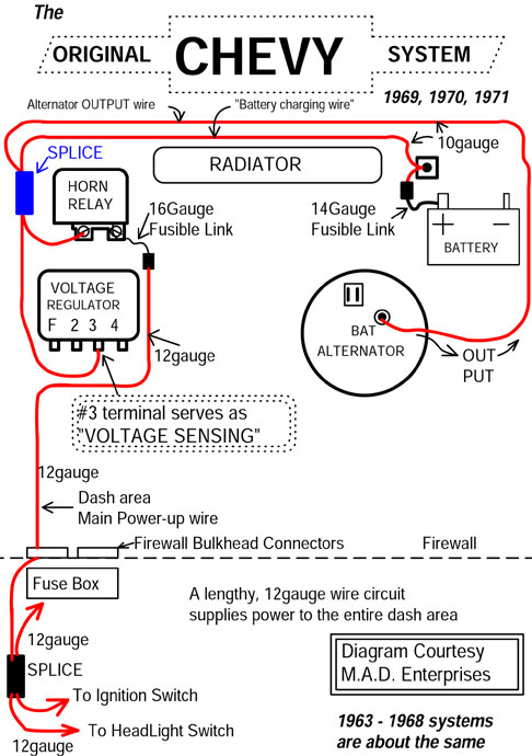
The
system diagramed above is typical of the original Chevy
wire harness design used in 1969,1970, and 1971.
Those years had the long nose water pump and
passenger side alternator mounting.
NOTE
that Chevy wiring from 1963 through 1968
was the same basic layout as shown in the diagram above,
only with the alternator at the driver’s side and with a
shorter wire from the alternator to the splice at the Horn
Relay area.
The entire electrical system gets power from the
“SPLICE” near
the Horn Relay, at the opposite side of the car from the
battery! Alternator
output is routed directly to the splice.
One of the wires from the splice delivers power to
the Horn Relay buss-bar, where the dash “main power
wire” is also connected.
The battery charging wire originates at the splice.
And vital to electrical system performance in this
original system, the voltage regulator will read and
adjust voltage level at the splice.
The splice is the center hub of this
electrical system, and maintaining proper voltage level at
the splice is the key to good performance with this
original system.
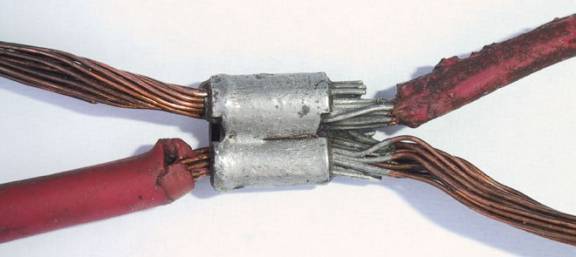
The
photo above shows the “SPLICE” in the wire harness,
which served as the “MAIN HUB” for distribution of
alternator power.
All power to operate the electrical system plus
power to recharge the battery is routed through this
splice.
This
type of factory splice is very reliable, as it is crimped
and soldered, and then covered with tape.
The splice is in the wire harness, along the
driver’s side fender, at the engine side of the radiator
core support.
“Buss-bar” is also correct terminology for a
common connection where wires come and go.
The splice in the wiring and the Horn Relay both
serve as buss-bars in this system.
All voltage regulators take a voltage reading,
and from the reading the regulator will make the correct
adjustments to alternator output.
THE UNIQUE PART OF THE CHEVY
SYSTEM
It’s
a rare occasion when a little resistance at a main wiring
circuit is helpful. And
it’s also a rare occasion when a system is improved
while violating what old institution has been teaching for
years. (And
sometimes delightful too, part of the fun with Hot Rodding
has always been sort rebel related.
Ha!)
Leading
authorities have often told us not to accept more than
0.4volts difference between the alternator and the
battery! In
fact DELCO REMY published engineering data for wiring the
components they built, instructing maximum of 0.5volts
difference between the alternator and battery, with the
alternator operating at maximum output.
Also
on the same engineering data sheet, DELCO REMY published
recommendation for minimum cable gauge sizes per feet of
cable between the alternator and the battery, and included
various alternator output ratings in the chart.
For alternator output ratings between 50 and 65
amps, the chart begins with 8gauge for total cable length
at 4 to 7feet. And by the time the total cable length grows to ’69 Camaro
dimensions, DELCO recommends 4gauge cable!
In this author’s many years of workshop
experience, an original GM built passenger car with larger
than 10gauge wire for 63amp alternators has never been
encountered.
The
instruction was intended to help with the wiring job to be
done by Chevy (and also other carmakers and companies who
might install DELCO REMY alternators). The engineering data was published as a guideline
to insure proper system operation when using the parts
built by DELCO REMY.
Sometimes these guidelines are intended as a cover
all blanket, work in all situations, and always get the
job done installation method.
(Guidelines are intended to keep people out of
trouble.) In
other words the provided recommendations are guidelines,
but not intended as solid, rigid,
“never-to-be-an-exception,” rule.
If
cars would have been entirely built using all minimum
engineering recommendations for copper cable gauge sizes,
then these cars would be hauling around a few hundred
pounds of very expensive copper cable.
Since it was not practical to install so much heavy
copper cable on the millions of cars built, Chevy
engineering provided a practical exception to the rule.
At
least one thing about wiring for this Chevy alternator
system is very unusual, excessive voltage drop between the
alternator and battery will occur with normal system
function—and yet the electrical system worked fine.
The battery charged perfectly and electrical system
performance was not compromised in the least bit.
It was a feat accomplished by the wiring system
layout. Not
only that, but it was a forgiving system that was more
gentle to batteries and alternators in the event of
recharging a battery while driving!
No
doubt those “rebel with a cause Chevy
engineers” who came up with this system knew exactly
what they were doing.
Truly the Chevy wiring system was unique.
The design caused the voltage regulator to take
voltage reading from the main power distribution hub (the
splice). The
heavy cable and minimum voltage drop recommendations from
DELCO would have worked, even without special attention to
where the voltage regulator would take voltage level
reading.
Mounting location of components caused long wire
length
at the alternator output circuit, and also at the battery
charging circuit.
These two wires deserve the most attention, in this
system.
Long lengths at these two wires give the Chevy
system special characteristics.
Component locations to be concerned with are the
battery, alternator, voltage regulator, and power
distribution “splice.”
(Please see “THE ORIGINAL CHEVY SYSTEM” diagram
above.)
THE ALTERNATOR OUTPUT WIRE (Please
refer to “The ORIGINAL CHEVY SYSTEM” diagram.)
When
current flow through long wires is a large amount, a “problem”
with significant voltage drop will occur.
But regarding voltage drop at the long length of
“alternator output wire,” the system was
self-compensating.
The regulator took voltage reading from the splice,
which distributed alternator power.
(“Voltage-Sensing was not from the alternator or
the battery!)
The regulator adjusted alternator output as
required to maintain proper voltage level at the splice.
Therefore a little voltage drop in a long wire from
the alternator did not reduce system performance.
The alternator did not mind producing power at
15.2volts, which allowed for a 1volt drop in the long
wire, to arrive with power at the “splice” at 14.2
volts level.
This
part of the system layout did not happen by chance.
The voltage sensing wire from the regulator was
connected where it would optimize system performance,
which let the main hub distribute power at 14.2volts.
It was a wiring design created with definite
purpose in mind.
Thanks to some clear thinkers at Chevy engineering
department we were spared some cost, and weight, and bulky
cables at the front of these cars!
Of
course the system would have worked equally well with
4gauge copper cable connecting the alternator to the horn
relay, and 4gauge connecting the alternator to the
battery.
And then, “voltage sensing” for the regulator
could have been connected anywhere in the main system–Or
even at the alternator itself (as with the “ONE-WIRE”
alternator).
But manufacturing the system with so many feet of
4gauge cable would have contributed to higher cost of
these cars!
And, the system with 4gauge cables would not have
performed any better than the Chevy system with only
10gauge wires.
(Also see our Tech Section feature on “REMOTE
VOLTAGE SENSING.”)
THE BATTERY CHARGING WIRE (Please
refer to “The ORIGINAL CHEVY SYSTEM” diagram.)
In
the case of voltage drop at the long “battery charging
wire,” the small amount of voltage drop was actually a
good thing.
In honest retrospect view of the long battery
charging wire, the beneficial side effect
caused by the long wire was probably not intentional.
More likely it resulted from location of the parts.
The battery tray was on the passenger side.
The driver’s side had the alternator, voltage
regulator and dash power hook-up at the Horn Relay.
The battery charging wire connected the battery at
the right to the rest of the system at the left.
Knowing that the battery would eventually become
charged and significant voltage drop would then disappear,
it’s likely that the engineering department simply
allowed it to happen.
Current
flow through the battery charging wire will only be a
large amount when the battery is discharged.
Therefore, significant voltage drop only occurred
when recharging a low battery.
This is when the beneficial side effect comes
into play; the voltage drop in the battery
charging wire slowed the battery charge rate.
Slow rate battery charging is less abusive to the
battery than a fast charge rate.
Slowing the charge rate a little can also reduce
the probability of alternator overheating damage when
recharging a low battery while driving.
And slow charge rate reduces corrosion at the
battery area of these good-looking Hot Rods!
The
battery stops accepting much current as it becomes fully
charged, and as current flow tapers off then voltage drop
is reduced.
Therefore a small amount of resistance at the long
battery charging wire does not prevent the battery from
becoming fully charged—it just takes a little longer to
recharge a “low” battery.
Brightness
of lights, strength of ignition, and performance of other
electrical system parts was not affected by voltage drop
in the battery charging wire—because the electrical
system did not draw power from the “charging wire” in
this Chevy system.
The electrical system draws power from the splice,
where voltage is controlled by the regulator.
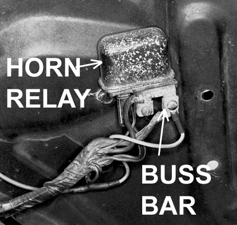
The
condition of connections at the Horn Relay screws is very
important to system operation.
The entire dash area will be operating with power
drawn from the screw connections, and they deserve
occasional inspection.
The metal bar at the base of the Horn Relay is
insulated from the body of the relay, it is full-time
“live,” and it is where the dash wiring connects to
power. Connections
at the buss-bar screws must be clean and tight.
Relays with a rusty or corroded buss-bar should be
replaced with new. Wire
terminals may be polished with a small wire brush.
When
Up-grading the alternator and using this original wiring
system, proper voltage must be maintained at the splice
and Horn Relay area.
It’s
a simple requirement, and more than one method may be used
to maintain the voltage needed for good electrical system
performance.
Please
click here
for Part 2 of THE CHEVY MAIN POWER SYSTEM
|